Quick guide on laser beam divergence measurement
Tuesday, July 11, 2023
Tuesday, July 11, 2023
Lasers are in demand for their well-collimated, single-wavelength electromagnetic beams. The low-divergence, single-wavelength radiation and vast range of available laser power ranges make them one of the most valuable tools for material processing in industry and research.
Laser beam divergence is one important parameter to know for laser manufacturers and users alike who need to take control of their laser spot size. From laser welding applications to wafer dicing or eye surgery, knowing your beam divergence is a must for building a functional setup and directing the energy precisely where it is needed for a given process.
Here we present important concepts about laser beam divergence measurement. Understanding them will help you avoid wasting your energy where it is not needed!
For a circular beam, divergence is defined as the angular measure of how the beam diameter increases with the distance from the laser aperture. It is measured in milliradians (mrad) or degrees (°). Simply put, it tells you how the beam grows from the source to the target.
Ensure you purchase the most optimal solution for your measurement needs with this checklist.
Download it now, it's helpful and free!
Laser beams diverge because they would require an infinitely thin and long cavity of atoms emitting photons in resonance along one single direction to get a collimated beam over an infinite distance. That’s just not how things work in real life: for example, considering the growing number of industrial applications such as welding, cutting, or cladding, using fiber lasers that have a large divergence at the fiber output, dealing with divergence is inevitable.
More precisely, divergence is defined as the angle at which the beam expands in the far field (i.e. at a distance from the beam focus which is much farther than the Rayleigh length) by using the middle of the beam waist as reference.
The Rayleigh length Zr is the distance along the propagation axis from the beam waist to the place where the area of the beam cross-section is doubled.
All of this can seem a little confusing regarding Rayleigh length and far field. So, the key point to remember is that the beam behaves differently when checked close to the waist or in a far field. In the far field, the divergence of the beam tends to be linear, while it is not the case at the waist, like you can see in Figure 1.

Figure 1: The divergence half angle in  x and y is defined as θ = Div/2.
By design, circular laser beams usually possess a Gaussian-shaped energy density distribution (or irradiance) from the center of the beam to the edges. You know, that bell-shaped curve telling you that most of the beam energy is located at the center of the beam, along the propagation axis.

Figure 2: theoretical Gaussian beam cross-section.
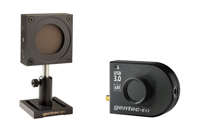
A proper laser beam profiling camera such as Beamage-4M will provide ISO-compliant beam size measurements such as the beam radius defined by the distance from the point of maximum energy density Emax in the energy distribution (at the center of the beam) to the point where the energy density equals Emax / e2.

Figure 3: Example of a Gaussian fit made on x and y in Gentec-EO PC-Beamage software on a real beam. The X and Y beam dimensions are derived from this fit.
Have a look for yourself! You can download and try out the PC-Beamage software for free along with the available simulated beams.
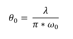
For a circular Gaussian beam, the minimum achievable value of divergence (half-angle) is given by this simple formula:

In the equation above, λ is your laser wavelength and ω0 is the beam natural waist: its smallest dimension along the z-axis.
A Gaussian laser beam is said to be diffraction-limited when the measured divergence is close to θ0. To achieve the best aiming performance, that’s the goal!
You can do the calculations yourself, but you could also use our free calculators. You have two choices here. It depends if you’re in a far field or close to the waist.
Gentec-EO's beam divergence and diameter calculator is publicly available and free to use. Bookmark the page and use it whenever it can save you time.
If you are working around the beam waist, try our spot size calculator instead. It will not provide divergence information but rather give you the beam size in that close field (the calculator assumes a perfectly collimated beam prior to the lens, see the Formulas section for more details).
One would think that moving the camera along the propagation axis of the laser is required to measure divergence but it actually isn’t!
We all have in mind that to obtain the M2 factor of a laser beam (also known as beam quality factor), one has to measure both the divergence θ and the beam waist ω0, which does require to move along the z-axis to actually find the waist and measure its size.
The M2 factor, which is dimensionless, is an indicator of the laser beam quality and quantifies how close your beam propagation is to the propagation of a theoretical Gaussian beam of the same wavelength.


Measuring the M2 factor requires the use of a moving stage for your beam profiler, along with lenses and alignment mirrors, which is available as a complete package thanks to the Gentec-EO automated Beamage-M2 system. It adds an extra layer of information about beam quality but here, we don’t need to obtain several beam diameter values along the z-axis to calculate divergence.
First step is to place an aberration-free focusing lens between your camera and the laser. The key is to place the lens in the far field of the laser beam and the camera sensor exactly at the focal point of the lens (not at the beam waist).
At this point, it’s all about calculations! According to the ISO11146:2005 standard, the divergence in both main axes (x and y) is given by:

ωf is the width of the focused spot at distance f from the lens and f is the focal length of your lens at the wavelength of your laser. Beware that focal length is wavelength-dependent, so make sure you get the correct value from the lens supplier.
This method applies to non-Gaussian beams as well. No need to measure beam diameters before or after the focal point; that’s the beauty of this setup. If you change your lens for another focal length, the size of the beam at focal point will be different but if your camera is well positioned at focal point, the measured divergence will be the same.
Now that you have installed and launched PC-Beamage on your computer, open the Divergence tab and have fun!
For example, with high-power fiber lasers, your sample is usually processed up close to the fiber output, but the divergence is controlled and modified by using optical scanners that provide the required beam size on the sample to be processed.
Collimators can also be used in low-power fiber laser applications such as in telecommunications applications and with various diode lasers.
Go ahead and test various optics to evaluate how they affect your laser beam size, now that you know how to measure divergence easily.
Natural divergence of laser beams is often harnessed to enlarge the beam size and comply with power density damage thresholds for power measurement with a laser power meter.

Do you need to make sure how to use your beam profiling camera the fastest/easiest way and verify your power densities for safe profiling and power measurement? Contact us with your laser specs!